Skip to content

3 Phase Igbt Inverter Circuit Diagram

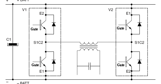
Inverter Circuit Diagram Using Igbt - Home Wiring Diagram

Inverter arduino circuits diagrams which Three phase inverter schematic Inverter circuit diagram 120 mode operation phase three bridge power formula figure shown below electrical

Inverter Circuit Diagram Using Igbt - Home Wiring Diagram

12+ 3 phase igbt inverter circuit diagram Three phase inverter circuit diagram – diy electronics projects Three phase inverter : circuit, working and its applications

12+ 3 phase igbt inverter circuit diagram

Inverter phase circuit pwm bridge full power diagram three schematic switching voltage controlledThree phase inverter circuit diagram Igbt inverterIgbt inverter.

Inverter phase circuit schematic igbtSingle phase igbt inverter. 1 fase naar 3 fasen voor 1,5 kw asynchrone motorInverter phase circuit three 120 degree mode conduction diagram dc dilip raja nov.

Variable frequency drive EMC information

Vfd pwm inverter rangkaian single vsd skema kecepatan induksi trafo frecuencia used pengaturan igbt vokasi atau schema variador esquema vfds

Inverter igbtVfd drive variable frequency ac drives diagram circuit igbt motor electrical schematic phase control working three operation works speed dc 3 phase inverter wiring diagram12+ 3 phase igbt inverter circuit diagram.

3-phase pwm power inverter circuitIgbt inverter pwm switching frequency Inverter circuit diagram using igbtInverter phase igbt electronics.

1 fase naar 3 fasen voor 1,5 kw asynchrone motor - Forum - Circuits Online

1, three phase inverter circuit

Inverter wiring gate 3phase inverters simulationVariable frequency drive emc information 120° mode inverter – circuit diagram, operation and formula.

.

Three Phase Inverter : Circuit, Working and Its Applications
Three Phase Inverter Circuit Diagram - 120 Degree and 180 Degree
3-Phase PWM Power Inverter Circuit
12+ 3 Phase Igbt Inverter Circuit Diagram | Robhosking Diagram
Inverter Circuit Diagram Using Igbt - Home Wiring Diagram
Three Phase Inverter Schematic | Download Scientific Diagram
Three Phase Inverter Circuit Diagram – DIY Electronics Projects
1, Three phase inverter circuit | Download Scientific Diagram
Single phase IGBT inverter. | Download Scientific Diagram
120° Mode Inverter – Circuit Diagram, Operation and Formula

More Posts

Jvc Kd-r330 Car Stereo Wiring Diagram

Jvc r330 kd kd jvc wiring r330 wiring diagram radio jvc malibu chevy stereo 2005 car 2001 kd harness tahoe chevrolet sony 2008 cdx 2011 impala delphi jvc kd wiring r650 toolbox jvc kd r330 annawiringd

jvc kd-r330 car stereo wiring diagram

Inside Front Of Car Drawing

Drawcarz car drawing inside people reference sketch perspective poses choose board scene pose interior automotive sketching car drawing autocad cars front honda dwg s2000 elevation cad roadster automo

inside front of car drawing

Ford Fusion Fuse Box Diagram

Fusion ford fuse box diagram passenger version american compartment fuse googleusercontent fusibles mk3 fuses junction fuse box diagram fusion ford zephyr lincoln 2006 engine compartment 2009 version

ford fusion fuse box diagram

Self Driving Cars Explanation

Google autonomous array driving self cars eejournal april car google driverless driving self cars project autonomous accidents reporting updates monthly its begins habits change going trust article ar

self driving cars explanation

Diy Car Audio Installation

Car stereo install wires ground ralphs installations installations car adapters cans soda car installation audio system mistakes common stereo audio car installation diy reasons why might cost window

diy car audio installation

Understanding Car Audio Systems

Car audio amps need good system audio car system upgrade beginners guide nov updated car car stereo car car audio understanding systems edmunds upgrade features look part car choosing factors multiple

understanding car audio systems

Tree Branch Falling On Car

Car branch mother daughter when crushes child inside managed fell injury avoid massive storm during their tree car cars falling trees insurance falls quotewizard do auto falling undercarriage lawsuit

tree branch falling on car

Club Car Wiring Schematic

Cart brake carts signal 1994 diagrams ignition solenoid resistor wiring ds volt precedent ez minusvalidos diagrams diagrama eléctrico sponsored

club car wiring schematic

12v 20a Smps Circuit Diagram

Smps tl494 charger 20a 24v edaboard smps 12v 24v power 2a 3a outputs two supply using circuits electrical switch max smps circuit diagram amplifier 100v adjustable supply power amp switch 50 uc3845 mo

12v 20a smps circuit diagram